

FCR7 SERIES
HYDRAULIC DIVISION FCR7 SERIES
FCR7 SERIES
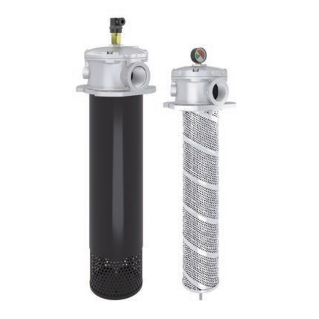
Tank top return filters
TECHNICAL INFORMATION
Return filter for mounting on the tank lid. Filtration from inside to outside.
Flow rates up to 600 l/min.
FCR7 SERIES 1/8
FILTER MEDIA: Microglass fiber: G03 - G06 - G10 - G25
Paper: C10 - C25
Wire mesh T60
DIFFERENTIAL BURST PRESSURE: 10 bar
OPERATING TEMPERATURE RANGE: -25°C +100°C
FLUID COMPATIBILITY: Full with HH-HL-HM-HV (acc. To ISO 2943).
For use with other fluid please contact Filtrec Customer Service
(info@filtrec.it).
HOUSING
ELEMENT tested according to ISO 2941, 2942, 2943, 3968, 16889, 23181
HYDRAULIC SYMBOL:
PRESSURE: Max working 8 bar
Burst 16 bar
CONNECTION PORTS: G 1/2”÷ G 2”
MATERIALS: Head and cover: aluminium alloy
Top cover: PA6 (sizes 10 to 14 only)
Insert holder: aluminium alloy
Diffuser: zinc plated steel
Seal: NBR
BYPASS: 1,7 bar
A
T
FCR7 SERIES 2/8
OVERALL DIMENSIONS
NOMINAL SIZE
HYDRAULIC DIVISION FCR7 SERIES
MODEL A H1 H2 R WEIGHT
FCR7-11 G 1/2"
G 3/4”
G 1”
G 1” 1/4
133 195 206 2 Kg
FCR7-12 178 250 2,2 Kg
FCR7-13 228 345 300 2,4 Kg
FCR7-14 328 400 2,8 Kg
Indicator port
2 holes M8
TANK MOUNTING PATTERN
H1
R
H2
option “S” with diffusor option “0” without diffusor
FCR-7 11 / 12 / 13 / 14
F
FCR7 SERIES 3/8
HYDRAULIC DIVISION FCR7 SERIES
OVERALL DIMENSIONS
NOMINAL SIZE
MODEL A H1 H2 R WEIGHT
FCR7-20 G 1”
G 1” 1/4
G 1” 1/2
233 310 330 5,3 Kg
FCR7-21 303 400 5,6 Kg
FCR7-22 508 515 515 6,9 Kg
MULTIFIX FLANGE ALLOWING TWO TANK MOUNTING PATTERNS
D1= 134 for option “S” / 131 for option “0”
FCR-7 20 / 21 / 22
F
option “S” with diffusor / option “0” without diffusor
H1
R
H2
Filling plug (optional)
Indicator port
175
D1
3 HOLES
M10
120°
45°
D1
175 ÷ 185
4 HOLES
M10
FCR7 SERIES 4/8
HYDRAULIC DIVISION FCR7 SERIES
OVERALL DIMENSIONS
FCR-7 30 / 31 / 32 / 33
o
option “S” with diffusor / option “0” without diffusor H2H1
Filling plug (optional)
Indicator port
R
220
D1
90°
30°
4 HOLES Ø
M10
4 HOLES
M12
D1
215÷ 220
MULTIFIX FLANGE ALLOWING TWO TANK MOUNTING PATTERNS
D1= 166 for option “S” / 161 for option “0”
NOMINAL SIZE
MODEL A H1 H2 R WEIGHT
FCR7-30
G 1” 1/2
G 2”
265 360 380 7,2 Kg
FCR7-31 345 460 7,5 Kg
FCR7-32 535 550 650 9,1 Kg
FCR7-33 445 560 9,8 Kg
FCR7 SERIES 5/8
HYDRAULIC DIVISION FCR7 SERIES
ORDERING INFORMATION
1. FILTER SERIES
3. FILTER MEDIA
6. BYPASS VALVE
4. SEALS
5. CONNECTIONS
10. INDICATOR PORT
11. INDICATOR
1. 2. 3. 4. 5. 6. 7. 8. 9. 10. 11.
FCR7 30 G10 B B6 B M S 0 C 000
R7 30 G10
FCR7
2. FILTER SIZE 11-12-13-14
20-21-22
30-31-32-33
B3 G 1/2”
B4 G 3/4”
B5 G 1”
B6 G 1 1/4”
B7 G 1 1/2”
B8 G 2”
C 1/8" plugged
7. MAGNET 0 no magnet
M with magnets
8. DIFFUSER 0 no diffuser
S with diffuser
9. FILLING PLUG 0 no filling plug
T with filling plug
000 no indicator
MPB (ex R9) press. gauge rear connection
MRB (ex R10) press. gauge radial connection
PDB (ex R13) pressure switch
G03 glassfiber ß4,5µm(c) > 1.000
G06 glassfiber ß7µm(c) > 1.000
G10 glassfiber ß12µm(c) > 1.000
G25 glassfiber ß22µm(c) > 1.000
C10 paper ß10µm(c) > 2
C25 paper ß25µm(c) > 2
T60 wire mesh 60 µm
B 1,7 bar
B NBR
SPARE ELEMENT
size 11 to 14
size 11 to 22
size 30 to 33
FCR7 SERIES 6/8
HYDRAULIC DIVISION FCR7 SERIES
PRESSURE DROP (∆p) INFORMATION FOR FILTER SIZING
HOUSING PRESSURE DROP
FCR7 11-14 FCR7 20-22
The total Delta P through a filter assembly is given from Housing Δp + Element Δp .
The max recommended total Δp for return filters is 0,4 – 0,6 bar with clean element.
The housing ∆p is given by the curve of the considered model and port, in correspondence of the flow rate value.
Flow rate (l/min)
∆p (bar)
FCR730-33
Flow rate (l/min)
∆p (bar)
Flow rate (l/min)
∆p (bar)
N.B. All the reported data have been obtained at our laboratory, according to specification ISO3968 with mineral oil
having 32 cSt viscosity and density 0,875 Kg/dm3.
FCR7 SERIES 7/8
ELEMENT PRESSURE DROP
The element Δp (bar) is given by the flow rate (l/min) multiplied by the factor in the table here below
corresponding to the selected media and divided by 1000.
If the oil has a viscosity V1different than 32 cSt a corrective factor V1/32 must be applied.
Example: 200 l/min with R722G10 and oil viscosity 46 cSt > 200 x 0,69/1000 x 46/32 = 0,20 bar
EXAMPLE OF TOTAL ∆p CALCULATION
FCR722G10BB6BMSC000 with 200 l/min and oil 46 cSt:
Housing Δp 0,18 bar + element Δp 0,20 bar (200 x 0,69/1000 x 46/32) = total assembly Δp 0,38 bar
HYDRAULIC DIVISION FCR7SERIES
BYPASS VALVE PRESSURE DROP
The bypass valve ∆p is given by the curve of the considered model and setting, in correspondence of the flow rate
value.
FCR7 11-14 FCR7 20-22
Flow rate (l/min)
∆p (bar)
FCR730-33
Flow rate (l/min)
∆p (bar)
Flow rate (l/min)
∆p (bar)
G03 G06 G10 G25 C10 C25 T60
R711 19,02 16,88 6,93 4,61 2,95 2,52 1,58
R712 11,68 10,81 4,32 3,10 2,93 2,50 1,36
R713 7,75 6,85 3,72 2,73 2,15 1,85 1,34
R714 5,52 4,95 2,38 2,18 1,74 1,49 1,32
R720 4,02 3,28 1,45 1,08 0,98 0,85 0,14
R721 2,61 2,21 1,09 0,85 0,76 0,65 0,12
R722 1,86 1,58 0,69 0,46 0,38 0,25 0,11
R730 3,12 2,49 1,34 0,92 0,84 0,70 0,10
R731 2,06 1,90 0,84 0,39 0,33 0,25 0,09
R732 1,31 1,19 0,49 0,26 0,23 0,18 0,08
R733 1,47 1,23 0,62 0,28 0,25 0,20 0,09
USER TIPS INSTALLATION
1
2
3
1
7
5
4
COVER
2 FILTER HEAD
3 FILTER ELEMENT
4 DIFFUSER
5 SEAL
6 INDICATOR PORT
7 IDENTIFICATION LABEL
1. the filter head must be properly positioned and
well secured on the tank lid through the fixing
holes
2. the hose must be properly connected to the IN
port
3. verify that no tension is present on the filter after
mounting
4. enough space must be available for filter
element replacement
5. the visual clogging indicator must be in a easily
viewable position
6. when a electrical indicator is used, make sure
that it is properly wired
7. keep in stock a spare FILTREC filter element for
timely replacement when required
OPERATION
1. the filter must work within the operating
conditions of pressure, temperature and
compatibility given in the first page of this data
sheet
2. the filter element must be replaced as soon as
the clogging indicator signals at working
temperature
3. If no clogging indicator is mounted, replace the
element according to the system manufacturer’s
recommendations
WARNING
Make sure that Personal Protective Equipment (PPE) is
worn during installation and maintenance operation.
DISPOSAL OF FILTER ELEMENT
The used filter elements and the filter parts dirty of oil
are classified as “Dangerous waste material”: they
must be disposed according to the local laws by
authorized Companies.
MAINTENANCE
1. before removing the top cover from the head,
ensure that the system is switched off and there
is no residual pressure in the filter
2. remove the top cover
3. remove the spring and extract the filter assembly
4. warning : a certain quantity of oil can be
retained within the filter element, provide to
have a proper container available for it
5. unscrew the nut at the bottom of the insert and
slip the dirty filter element carefully
6. Clean the tie rod (and the magnets if present)
and check the support gaskets conditions,
replace them if necessary.
7. Fit a new FILTREC element over the tie rod
and block it by tightening the bottom nut
8. put the insert assembly into the head, put the
spring in its position over the insert support,
then mount the top cover and secure it
properly
9. the used filter elements cannot be cleaned and
re-used
INDICATOR TIGHTENING TORQUE
10 Nm
FIXING BOLTS TIGHTENING TORQUE
M6 10 Nm
M8 25 Nm
M10 50 Nm
FCR7 SERIES 8/8
HYDRAULIC DIVISION FCR7 SERIES
CT09-rev.00-05/20
Technical information may change without notice