

FR6 SERIES
HYDRAULIC DIVISION FR6 SERIES
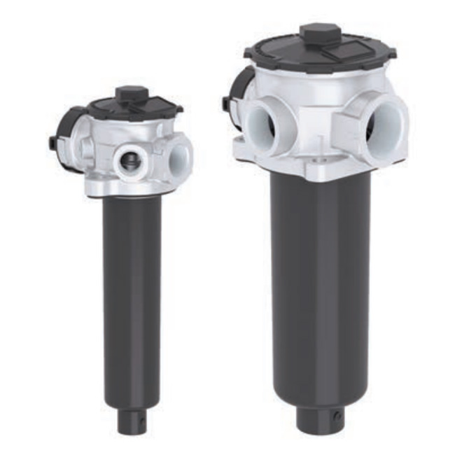
FR6 SERIES
Tank top return filters
TECHNICAL INFORMATION
The FR6 filters are available with various configurations:
• With or without inbuilt air breather
• With 2, 4 or 6 tank mounting holes
• With or without supplementary inlet ports
• Flow rate up to 300 l/min
FR6 SERIES 1/12
HYDRAULIC SYMBOL:
PRESSURE: Max operating: 10 bar
CONNECTION PORTS: Main ports: G ¾” to 1 ¼“
Additional ports (optional): G ½” to 1”
MATERIALS: Head: aluminium alloy
Bowl and top cover: PA6 reinforced
Seals: NBR
BYPASS: Inbuilt in the filter element
B version 1,7 bar
C version 3 bar
FILTER MEDIA: Inorganic microfiber G06 - G10 - G15 - G25 - G40
Paper C10
Metal wire mesh T60
Synthetic M05 - M10 - M15
DIFFERENTIAL COLLAPSE PRESSURE: 10 bar
OPERATING TEMPERATURE RANGE: -25°C +100°C
FLUID COMPATIBILITY: Full with HH-HL-HM-HV (acc. To ISO 2943).
For use with other fluid please contact Filtrec Customer Service
(info@filtrec.it).
HOUSING
ELEMENT tested according to ISO 2941, 2942, 2943, 3968, 16889, 23181
tested according to NFPA T3.10.5.1 , ISO3968
A A A1 A2
T T
FR6 SERIES 2/12
A1
A2
A
B
C
B
D
B
2 MOUNTING HOLES
NOMINAL SIZE
HYDRAULIC DIVISION FR6 SERIES
FR62R101
G 3/4” G 1/2” 84 - 88 26 51 62 64 60 - 64 11 59 25
104 77 200 0,8
FR62R102 168 77 265 0,8
FR62R104 201 77 300 0,9
FR62R120
G 1”
G 1 1/4”
G 1” 114 - 116 32 70 78 80 87 - 91 11 86 40
87 96 210 1,0
FR62R122 132 96 260 1,0
FR62R130 214 96 340 1,1
FR62R131 318 96 440 1,2
MODEL A A1-A2
OPTIONAL
Ø B1 B2 B3 B4 B5 Ø D1 D2 Ø D3 Ø D4 H1 H2 R WEIGHT
Kg
A1+A2= ON REQUEST ONLY
B= INDICATOR PORTS
C= VERSION WITH AIR BREATHER
D= VERSION WITHOUT AIR BREATHER
FR6 SERIES 3/12
HYDRAULIC DIVISION FR6 SERIES
A1
A2
A
B
C
B
D
B
4 MOUNTING HOLES
NOMINAL SIZE
FR64R101
G 3/4” G 1/2” 84 - 88 26 51 62 64 60 - 64 11 59 25
104 77 200 0,9
FR64R102 168 77 265 0,9
FR64R104 201 77 300 1,0
FR64R120
G 1”
G 1 1/4”
G 1” 114 - 116 32 70 78 80 87 - 91 11 86 40
87 96 210 1,1
FR64R122 132 96 260 1,1
FR64R130 214 96 340 1,2
FR64R131 318 96 440 1,3
MODEL A A1-A2
OPTIONAL
Ø B1 B2 B3 B4 B5 Ø D1 D2 Ø D3 Ø D4 H1 H2 R WEIGHT
Kg
A1+A2= ON REQUEST ONLY
B= INDICATOR PORTS
C= VERSION WITH AIR BREATHER
D= VERSION WITHOUT AIR BREATHER
FR6 SERIES 4/12
HYDRAULIC DIVISION FR6 SERIES
D4
2
B2
A
D3
H2 H1
R
B3
D2
D1
B1
45°
45°
A
B
B
B
B4
6 MOUNTING HOLES
NOMINAL SIZE
FR66R120
G 1”
G 1 1/4”
114 - 116 32 70 60 80 87-91 11 86 40
87
96
210 1,0
FR66R122 132 260 1,0
FR66R130 214 340 1,1
FR66R131 318 440 1,2
MODEL A Ø B1 B2 B3 B4 B5 Ø D1 D2 Ø D3 Ø D4 H1 H2 R WEIGHT
Kg
B= INDICATOR PORTS
can fit both 2 or 4 holes tank mounting pattern
1. 2. 3. 4. 5. 6. 7. 8. 9. 10. 11. 12.
FR6 2 R1 30 G15 C B B6 00 1 B R9
R1 30 G15 C
FR6 SERIES 5/12
ORDERING INFORMATION
1. FILTER SERIES
SPARE ELEMENT
2. TANK MOUNTING HOLES
3. FILTER ELEMENT SERIES
4. FILTER SIZE
5. FILTER MEDIA
6. BYPASS VALVE
7. SEALS
8. MAIN PORT
9. ADDITIONAL PORTS
10. INBUILT AIR BREATHER
11. INDICATOR PORTS
12. CLOGGING INDICATORS
ACCESSORIES
FR6
2 2 holes
4 4 holes
6 2 + 4 holes
B4 G 3/4” (for size 01-02-04)
B5 G 1”
B6 G 1 1/4”
00 no additional port
B3 2 x G 1/2 (for size 01-02-04)
B5 2 x G 1 (for size 20-22-30-31)
0 no air breather
1 with air breather (not for FR66)
B 2 x G 1/8”
000 without indicator
R9 (MPB) pressure gauge (for “B” bypass)
MPC pressure gauge (for “C” bypass)
R13 (PDB) pressure switch (for “B” bypass)
R14 (PDC) pressure switch (for “C” bypass)
LC24 LED connector for pressure switch
DS350 Dipstick
ET0250 Extension tube 250 mm long
ET0500 Extension tube 500 mm long
ET2250 Extension tube 250 mm long
ET2500 Extension tube 500 mm long
B610F03 Spare air breather
R1
01-02-04
20-22-30-31
B 1,7 bar (for paper and wire mesh elements)
C 3 bar (for glassfiber elements)
B NBR
(available for 2 and 4 holes version only)
(for size 20-22-30-31)
(for size 01-02-04)
(for size 20-22-30-31)
The accessories must be ordered
separately
HYDRAULIC DIVISION FR6 SERIES
G06 glassfiber ß7µm(c) > 1.000
G10 glassfiber ß12µm(c) > 1.000
G15 glassfiber ß17µm(c) > 1.000
G25 glassfiber ß22µm(c) > 1.000
G40 glassfiber ß35µm(c) > 1.000
C10 paper ß10µm(c) > 2
T60 wire mesh 60 µm
M05 synthetic ß10µm(c) > 1.000
M10 synthetic ß15µm(c) > 1.000
M15 synthetic ß20µm(c) > 1.000
FR6 SERIES 6/12
HYDRAULIC DIVISION FR6 SERIES
PRESSURE DROP (∆p) INFORMATION FOR FILTER SIZING
HOUSING PRESSURE DROP
FR6x R101-02-04
FR6x R130-31
FR6x R120-22
The total Delta P through a filter assembly is given from Housing ∆p + Element ∆p.
The max recommended total ∆p for return filters is 0,4 – 0,6 bar with clean element.
For multiport versions, the housing ∆p to be considered is the sum of the ∆p through all the ports that can be
used contemporarily.
N.B. All the reported data have been obtained at our laboratory, according to specification ISO3968 with
mineral oil having 32 cSt viscosity at 40°C and density 0,875 kg/dm3.
The housing ∆p is given by the curve of the considered model and port, in correspondence of the flow rate value.
FR6 SERIES 7/12
HYDRAULIC DIVISION FR6 SERIES
ELEMENT PRESSURE DROP
The element ∆p (bar) is given by the flow rate (l/min) multiplied by the factor in the table here below
corresponding to the selected media and divided by 1000.
If the oil has a viscosity V1different than 32 cSt a corrective factor V1/32 must be applied.
Example: 80 l/min with R130G10B and oil viscosity 46 cSt > 80 x 3,19/1000 x 46/32 = 0,36 bar
EXAMPLE OF TOTAL ∆p CALCULATION
FR62R130G10BBB6001B000 with 80 l/min and oil 46 cSt:
Housing ∆p 0,01 bar + element ∆p 0,36 bar (80 x 3,19/1000 x 46/32) = total assembly ∆p 0,37 bar
G06 G10 G15 G25 G40 C10 T60 M05 M10 M15
R101 26,84 15,20 10,04 8,37 4,32 4,59 2,43 9,94 8,49 5,30
R102 13,16 8,22 4,94 4,55 2,63 2,88 0,82 5,37 4,59 3,03
R104 10,96 6,41 4,00 3,82 2,02 2,45 0,79 4,27 3,65 1,79
R120 13,85 8,65 6,44 6,32 2,77 4,09 0,86 5,65 4,83 3,19
R122 7,80 5,27 3,92 3,60 1,55 2,70 0,76 3,83 3,27 1,79
R130 5,09 3,19 2,25 2,06 0,90 1,64 0,49 2,31 1,98 1,02
R131 3,34 1,94 1,37 1,26 0,46 1,06 0,24 1,41 1,20 0,63
BYPASS VALVE PRESSURE DROP
The bypass valve ∆p is given by the curve of the considered model and setting, in correspondence of the flow rate
value.
FR6x R101-02-04 FR6x R120-22-30-31
FR6 SERIES 8/12
HYDRAULIC DIVISION FR6 SERIES
ACCESSORIES
These accessories fit all our standard models and must be ordered separately.
AIR BREATHER
DIPSTICK for oil level detection
When reduced space available, one of the tank fixing
hole can be used for a dipstick to check the oil level; it is
supplied with a M10 bolt support.
EXTENSION TUBE
The flow from the filter must come out below the oil level
to avoid possible generation of free air or foam.
When necessary an extension tube can be fitted onto the
knobs of the bowl end.
B
A
TECHNICAL DATA
FILTRATION FLOW RATE DELTA P REPLACEMENT PART NR.
3 µm up to 300 Nl/min 50 mbar B610F03
N.B. we recommend to replace the air breather when replacing the oil filter element
(when working in a very dirt environment, a more frequent air breather replacement
could be necessary)
Part nr. A
DS350 350
DIPSTICK
Part nr. B
for size 01, 02, 04
ET0250 250
ET0500 500
for size 20, 22, 30, 31
ET2250 250
ET2500 500
EXTENSION TUBE
FR6 SERIES 9/12
HYDRAULIC DIVISION FR6 SERIES
OVERVIEW
INBUILT AIR BREATHER
Version available
2 ADDITIONAL PORTS
Version available
DIPSTICK
Available for all models
EXTENSION TUBE
Available for all models
2 TANK
MOUNTING
HOLES
4 TANK
MOUNTING
HOLES
6 TANK
MOUNTING
HOLES
(can fit both 2 or 4
holes mounting pattern)
FR62 and FR64 are available in a version with inbuilt air breather for compact solution.
FR62 and FR64 are also available in multiport version with 2 extra IN ports for additional return flows in the same filter.
All the FR6 can fit as options:
- Extension tube to ensure flow outlet below the minimum oil level, thus avoiding formation of foam
- Dipstick for oil level detection, convenient in compact application avoiding the need of a side visual level gauge.
FR6 return filters are available to fit 2 (FR62) or 4 (FR64) tank mounting patterns; FR66 can fit both mounting patterns.
1
2
3
4
1
1
2
2
3
4
4 4
FR6 SERIES 10/12
HYDRAULIC DIVISION FR6 SERIES
USER TIPS INSTALLATION
1
2
3
3
1
6
7
8
5
4
COVER
2 SPRING
3 O-RING
4 FILTER ELEMENT
5 FILTER BOWL
6 FILTER HEAD
7 SHAPED GASKET
8 AIR BREATHER
1. the gasket (7) must be properly positioned and
the head (6) well secured on the tank lid through
the fixing holes
2. the hose must be properly connected to the IN
port
3. the OUT port must be clear (an extension tube
could be fitted, if needed for having the outlet
below the oil level)
4. verify that no tension is present on the filter after
mounting
5. when present the air breather (8), it must be in
a protected position
6. enough space must be available for filter
element replacement
7. the visual clogging indicator must be in a easily
viewable position
8. when a electrical indicator is used, make sure
that it is properly wired
9. keep in stock a spare FILTREC filter element for
timely replacement when required
OPERATION
1. the filter must work within the operating
conditions of pressure, temperature and
compatibility given in the first page of this data
sheet
2. the filter element must be replaced as soon as
the clogging indicator signals at working
temperature (in cold start conditions, oil
temperature lower than 30°C, a false alarm
can be given due to oil viscosity)
3. If no clogging indicator is mounted, replace the
element according to the system manufacturer’s
recommendations
WARNING
Make sure that Personal Protective Equipment (PPE) is
worn during installation and maintenance operation.
DISPOSAL OF FILTER ELEMENT
The used filter elements and the filter parts dirty of oil
are classified as “Dangerous waste material”: they
must be disposed according to the local laws by
authorized Companies.
MAINTENANCE
1. before removing the cover (1), ensure that the
system is switched off and there is no residual
pressure in the filter
2. unscrew the cover (1) by turning it anti‐clockwise
and remove it
3. remove the spring (2) first, then the dirty element
(4) and the bowl (5)
4. clean the bowl (5) and fit a new FILTREC
element (4), verifying the part number,
particularly concerning the micron rating
5. when fitting the new element (4), open its plastic
protection on the open end side and insert it
onto the spigot in the filter bowl, then remove
completely the plastic protection
6. check the O‐ring (3) conditions and replace if
necessary
7. put the spring (2) in its position on the filter
element
8. screw the cover (1) by turning it clockwise,
tighten at the recommended torque
9. the used filter elements cannot be cleaned and
re‐used
COVER TIGHTENING TORQUE
20 Nm
INDICATOR TIGHTENING TORQUE
10 Nm
CT82-rev.02-03/21
Technical information may change without notice
HYDRAULIC DIVISION FR6 SERIES
FR6 SERIES 12/12
www.filtrec.com