

FS7 SERIES
HYDRAULIC DIVISION FS7 SERIES
FS7 SERIES
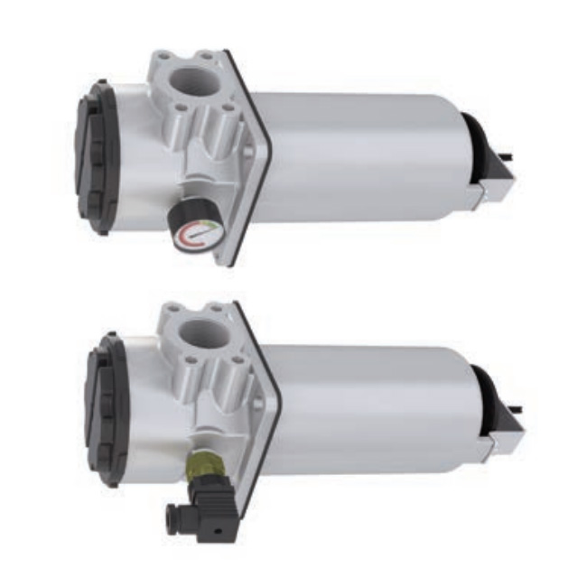
Side wall mounting suction filters
TECHNICAL INFORMATION
Suction filter for mounting on the tank side wall. the shut-off valve allows
filter element replacement without opening or emptying the reservoir.
Flow rates up to 200 l/min.
FS7 SERIES 1/8
HYDRAULIC SYMBOL:
CONNECTION PORTS: G 1" - G 1 1/4” - G 1 1/2” - SAE flange 1 1/2" 3000 psi
MATERIALS: Cover: PA6 polyammide
Housing: aluminium alloy
Seal: NBR (FKM on request)
BYPASS: No by-pass or 0,3 bar setting
FILTER MEDIA: Cellulose C10 - C25
Wire mesh T60 - T125 - T250
OPERATING TEMPERATURE RANGE: -25°C +100°C
FLUID COMPATIBILITY: Full with HH-HL-HM-HV (acc. To ISO 2943).
For use with other fluid please contact Filtrec Customer Service
(info@filtrec.it).
HOUSING
ELEMENT tested according to ISO 2941, 2942, 2943, 3968, 16889, 23181
FS7 SERIES 2/8
OVERALL DIMENSIONS
HYDRAULIC DIVISION FS7 SERIES 43
IN
THREAD CONNECTION
OUT
OUT
IN
Element removal
330
Element removal
330
373
82
Ø115
10,5
1/8" BSP
125
Main port
D1
OUT
Ø165
Ø150
90°
Main port
140
Ø115
373
10.5
125
1/8" BSP
82
43
Ø165
Ø150
1” BSP
1” BSP
Supplementary port
Supplementary port
Ø 11x18,5
nr. 4 slotted holes
Ø 11x18,5
nr. 4 slotted holes D1
140
D1
69,9 D1 35,7
FLANGE CONNECTION
F7=1 1/2” SAE J518 - 3000/M12
Indicator ports Indicator port
Indicator port
Indicator port Indicator port Indicator port
TANK MOUNTING PATTERN
M10
Ø116+
0
Ø150
5
- Ø165
D1
M12
D1 MAIN PORT
B5 1” BSP
B6 1 1/4” BSP
B7 1 1/2” BSP
SINGLE PORT TRIPLE PORT
FS7 SERIES 3/8
HYDRAULIC DIVISION FS7 SERIES
ORDERING INFORMATION
1. FILTER SERIES
3. FILTER MEDIA
6. BYPASS VALVE
4. SEALS
5. CONNECTIONS
9. INDICATOR
1. 2. 3. 4. 5. 6. 7. 8. 9.
FS7 41 C10 B B7 B M P PSD
S7 41 C10
FS7
2. FILTER SIZE 41
B5 G 1”
B6 G 1 1/4”
B7 G 1 1/2”
F7 SAE flange 1 1/2” 3000 psi
C5 3 x G 1”
C6 G 1 1/4” + 2 x G 1”
C7 G 1 1/2” + 2 x G 1”
G7 SAE flange 1 1/2” + 2 x G 1”
000 no indicator
MPS (ex S1) vacuum gauge scale 0÷-1 bar
PDS (ex S13) vacuum switch -0,2 bar
000 no element
C10 paper ß10µm(c) > 2
C25 paper ß25µm(c) > 2
T60 wire mesh 60 µm
T125 wire mesh 125 µm
T250 wire mesh 250 µm
0 no by-pass
B 0,3 bar
7. MAGNET 0 no magnet
M with magnet
8. INDICATOR PORT P rear (standard)
T right + rear + left (single port only)
B NBR
SPARE ELEMENT
ACCESSORIES LC24 LED connector
The accessories must be ordered
separately
FS7 SERIES 4/8
HYDRAULIC DIVISION FS7 SERIES
PRESSURE DROP (∆p) INFORMATION FOR FILTER SIZING
HOUSING PRESSURE DROP
FS7 41
The total Delta P through a filter assembly is given from Housing Δp + Element Δp.
The max recommended total Δp for suction filters is 0,15 bar with clean element.
The housing ∆p is given by the curve of the considered model and port, in correspondence of the flow rate value.
ELEMENT PRESSURE DROP
The element Δp (bar) is given by the flow rate (l/min) multiplied by the factor in the table here below
corresponding to the selected media and divided by 1000.
If the oil has a viscosity V1different than 32 cSt a corrective factor V1/32 must be applied.
Example: 80 l/min with S741T60 and oil viscosity 46 cSt > 80 x 0,075/1000 x 46/32 = 0,09 bar
EXAMPLE OF TOTAL ∆p CALCULATION
FS741T60BB7BMPPSD with 80 l/min and oil 46 cSt
Housing Δp 0,02 bar + element Dp 0,09 bar (80 x 0,075/1000 x 46/32) = total assembly Δp 0,11 bar
C10 C25 T60 T125 T250
S741 0,375 0,100 0,075 0,050 0,003
Flow rate (l/min)
∆p (bar)
FS7 SERIES 5/8
N.B. All the reported data have been obtained at our laboratory, according to specification ISO3968 with mineral oil
having 32 cSt viscosity and density 0,875 Kg/dm3.
BYPASS VALVE PRESSURE DROP
The bypass valve ∆p is given by the curve of the considered model and setting, in correspondence of the flow rate
value.
FS7 41
Flow rate (l/min)
∆p (bar)
HYDRAULIC DIVISION FS7 SERIES
USER TIPS INSTALLATION
1
2
7
1
6
5
4
COVER
2 HOUSING
3 FIXING HOLES
4 SEAL
5 FILTER ELEMENT
6 BY-PASS VALVE
7 SHUT-OFF VALVE
8 MAGNETIC COLUMN
9 INDICATOR PORT
1. the filter housing (2) must be properly
positioned and well secured on the tank side
wall through the fixing holes
2. the OUT port must be properly connected to
the suction line
3. verify that no tension is present on the filter after
mounting
4. enough space must be available for filter
element replacement
5. the visual clogging indicator must be in a easily
viewable position
6. when a electrical indicator is used, make sure
that it is properly wired
7. keep in stock a spare FILTREC filter element for
timely replacement when required
OPERATION
1. the filter must work within the operating
conditions of pressure, temperature and
compatibility given in the first page of this data
sheet
2. the filter element must be replaced as soon as
the clogging indicator signals at working
temperature
3. If no clogging indicator is mounted, replace the
element according to the system manufacturer’s
recommendations
WARNING
Make sure that Personal Protective Equipment (PPE) is
worn during installation and maintenance operation.
DISPOSAL OF FILTER ELEMENT
The used filter elements and the filter parts dirty of oil
are classified as “Dangerous waste material”: they
must be disposed according to the local laws by
authorized Companies.
MAINTENANCE
1. before removing the top cover (1) from the
housing (2), ensure that the system is switched
off and there is no residual pressure in the filter
2. unscrew the cover (1) by turning it anticlockwise
3. remove the dirty element (5) by pulling it
carefully
4. fit a new FILTREC element(5), verifying the
part number, particularly concerning the micron
rating
6. check the seal (4) conditions and replace if
necessary
7. lubricate the threads and screw completely the
cover (1) in the filter housing by turning it
clockwise
8. the used filter elements cannot be cleaned and
re-used
INDICATOR TIGHTENING TORQUE
10 Nm
FS7 SERIES 6/8
HYDRAULIC DIVISION FS7 SERIES
8
9
3
SPARE SEAL KIT PART NUMBER
NBR 07.010.00238
4
CT35-rev.00-07/20
Technical information may change without notice FS7 SERIES 8/8
HYDRAULIC DIVISION FS7 SERIES